QEMU internals
A series of posts about QEMU internals:
A deep dive into QEMU: PCI slave devices
In the first PCI article we covered the host bridge part. Now that we have a clear overview of the QEMU PCI subsystem, let’s have a look at how PCI devices really work.
We will focus on the slave part of the CPIOM PCI components:
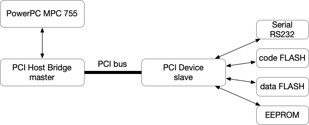
PCI slave device: MXFC
This component is a multi-purpose PCI device. It provides flash and
serial support. For illustration purpose, we choose to call this PCI
device MXFC.
typedef struct MXFCState {
    PCIDevice     parent_obj;
    uint8_t       _reg[MXFC_BAR3_SIZE];
    FILE          *serial;

    struct _nvm_regions {
        cpiom_nvm_code_t code;
        cpiom_nvm_data_t data;
        cpiom_nvm_data_t eeprom;
    } nvm;

    struct _memory_regions {
        MemoryRegion reg;
        MemoryRegion dgo;
    } mm;

} MXFCState;
We have dedicated objects for flash representation (uncovered here)
and a FILE handler for the serial port. We log received serial
characters to a file.
The device specification has several BARs which map the following:
- BAR0, code flash
- BAR1, data flash
- BAR2, eeprom
- BAR3, various configuration registers
The BARs are exposed through our device PCI config space, but there value might be changed by an OS driver at runtime. As they refer to the location of memory mapped device registers, there should exist a QEMU internal moulinette to inform the related emulated devices of their possible relocation. We will see how in this post.
Device initialization
As for usual QOM devices:
static void mxfc_class_init(ObjectClass *klass, void *data)
{
    PCIDeviceClass *k  = PCI_DEVICE_CLASS(klass);
    DeviceClass    *dc = DEVICE_CLASS(klass);

    k->realize   = mxfc_realize;
    k->vendor_id = PCI_VENDOR_ID_MXFC;
    k->device_id = PCI_DEVICE_ID_MXFC;
    k->revision  = PCI_DEVICE_REV_ID_MXFC;
    k->class_id  = PCI_CLASS_OTHERS;
    k->config_write = mxfc_config_space_write;
}

static const TypeInfo mxfc_type_info = {
    .name          = TYPE_MXFC_PCI_DEVICE,
    .parent        = TYPE_PCI_DEVICE,
    .instance_size = sizeof(MXFCState),
    .instance_init = mxfc_init,
    .class_init    = mxfc_class_init,
    .interfaces    = (InterfaceInfo[]) {
        { INTERFACE_CONVENTIONAL_PCI_DEVICE },
        { },
    },
};
We have the standard type declaration followed by default values to
appear in the device PCI config space at runtime (device, vendor,
revision, …). Notice that we overload the default config_write
callback for PCI config space access.
Additional setup is done in mxfc_realize, because at this step when
device is realized, the PCI device config space buffers are
allocated and we can access them safely:
static void mxfc_realize(PCIDevice *pci, Error **errp)
{
    DeviceState *dev = DEVICE(pci);
    MXFCState   *t   = MXFC_PCI_DEVICE(dev);
    uint8_t     *conf;

    conf = pci->wmask;
    pci_set_word(conf + PCI_STATUS,  0xf800);
    pci_set_word(conf + PCI_COMMAND, 0x141);

    conf = pci->config;
    pci_set_word(conf + PCI_STATUS, 0x480);
    pci_set_word(conf + PCI_COMMAND, 0x1c2);
    pci_set_long(conf + PCI_BASE_ADDRESS_0, MXFC_BAR0_DFT);
...
}
We can define bitmasks for words stored in that space. I let you have
a look at
PCIDevice
type definition.
Data flash and EEPROM
We then init data and eeprom flash components. We won’t detail their
specific device implementation. We here use
pci_register_bar
to tell QEMU that their respective mmio region is linked to a
BAR. Whenever BAR1 or BAR2 will be updated in the MXFC PCI config
space, the underlying mmio regions of nvm_data and nvm_eeprom
will be remapped to their new location … much appreciated.
/* BAR1 FLASH data */
cpiom_nvm_data_init(&t->nvm.data, "mxfc-flash-data",
                    OBJECT(t), MXFC_BAR1_SIZE);

pci_register_bar(pci, 1,
                 PCI_BASE_ADDRESS_SPACE_MEMORY |
                 PCI_BASE_ADDRESS_MEM_TYPE_32,
                 &t->nvm.data.mem);

/* BAR2 EEPROM */
cpiom_nvm_eeprom_init(&t->nvm.eeprom, "mxfc-eeprom",
                      OBJECT(t), MXFC_BAR2_SIZE);

pci_register_bar(pci, 2,
                 PCI_BASE_ADDRESS_SPACE_MEMORY |
                 PCI_BASE_ADDRESS_MEM_TYPE_32,
                 &t->nvm.eeprom.mem);
Code flash
The code flash BAR0 setup has some extra configuration steps. The device specification gives a default location and size:
#define MXFC_BAR0_DFT    (0xfc000000)
#define MXFC_BAR0_SIZE   (64<<20)
This is the area where the PowerPC CPU fetches initial instructions at
bootup. Unfortunately, we cannot use pci_register_bar this time for
several reasons. One of them is that the mmio mappings are not
effective until an explicit access to the PCI config space that
usually happens in driver code. As previously said, the very first
instructions are fetched in this area so it must be available
immediatly after power on.
We thus directly map the region in the PCI address space:
/* BAR0 FLASH code */
cpiom_nvm_code_init(&t->nvm.code, MXFC_FLASH_BLK_NAME,
                    OBJECT(t), MXFC_BAR0_SIZE);

memory_region_add_subregion_overlap(pci_get_bus(pci)->address_space_mem,
                                    MXFC_BAR0_DFT,
                                    &t->nvm.code.mem, 1);
If you remember, during device initialization we overloaded the
config_write callback with our own implementation. It looks like :
static void mxfc_config_space_write(PCIDevice *pci_dev, uint32_t addr,
                                    uint32_t val, int len)
{
    if (addr == PCI_BASE_ADDRESS_0)
        return;

    pci_default_write_config(pci_dev, addr, val, len);
}
We ignore access to BAR0 because it is already in place and has no reason to be modified (in our CPIOM environment). For other BARs, we just call the original default handler.
BAR access and updated mappings
When a target instruction writes to the PCI config space, usually the
pci_default_write_config
mmio handler is called:
void pci_default_write_config(PCIDevice *d, uint32_t addr, uint32_t val_in, int l)
{
...
    if (ranges_overlap(addr, l, PCI_BASE_ADDRESS_0, 24) ||
        ranges_overlap(addr, l, PCI_ROM_ADDRESS, 4) ||
        ranges_overlap(addr, l, PCI_ROM_ADDRESS1, 4) ||
        range_covers_byte(addr, l, PCI_COMMAND))
        pci_update_mappings(d);
...
}
As we can see, if the write operation hits a BAR, the
pci_update_mappings
function is called and will update the corresponding memory subregion:
static void pci_update_mappings(PCIDevice *d)
{
...
    r = &d->io_regions[i];
    new_addr = pci_bar_address(d, i, r->type, r->size);
    if (r->addr != PCI_BAR_UNMAPPED) {
        memory_region_add_subregion_overlap(r->address_space,
                                            r->addr, r->memory, 1);
...
}
Everything here is directly supported by QEMU as part of the PCI subsystem and let the developpers focus only on device specificities.